Dosya:Two-Slit Diffraction.png

Tam çözünürlük ((1.280 × 1.024 piksel, dosya boyutu: 291 KB, MIME tipi: image/png))
Bu dosya Wikimedia Commons'ta bulunmaktadır. Dosyanın açıklaması aşağıda gösterilmiştir. Commons, serbest/özgür telifli medya dosyalarının bulundurulduğu depodur. Siz de yardım edebilirsiniz. |
Özet
| Açıklama |
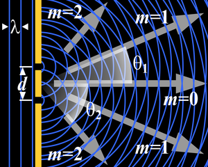
This is a drawing explaining two-slit diffraction: Planar wavefronts with wavelength λ (straight, vertical blue lines in the left-hand side of the image) arrives from the left at a barrier (thick yellow line) which have two slits or holes in it, at a distance d from each other. On the right-hand side of the barrier, the circular wavefronts that "leak" through the slits interfere with one another. This causes the light to scatter so that in certain directions, called orders (gray arrows labeled m0, m1, and m2), the light "concentrates" in beams while little or no light is emitted in the directions in between these orders. This image was rendered using the Persistence Of Vision Raytracer (POV-Ray for short) and the image description below. Note that to render this image, your POV-Ray installation needs to have access to the TrueType™ fonts timesbi.ttf (Times New Roman, bold & italic), timesbd.ttf (Times New Roman, bold), and symbols.ttf (various symbols, including greek letters), in order to render the white letters and numbers shown in the image. |
| Tarih | 25 Aralık 2005 (original upload date) |
| Kaynak | No machine-readable source provided. Own work assumed (based on copyright claims). |
| Yazar | No machine-readable author provided. Peo~commonswiki assumed (based on copyright claims). |
Lisanslama

|
Bu belgenin GNU Özgür Belgeleme Lisansı, Sürüm 1.2 veya Özgür Yazılım Vakfı tarafından yayımlanan sonraki herhangi bir sürüm şartları altında bu belgenin kopyalanması, dağıtılması ve/veya değiştirilmesi için izin verilmiştir;
Değişmeyen Bölümler, Ön Kapak Metinleri ve Arka Kapak Metinleri yoktur. Lisansın bir kopyası GNU Özgür Belgeleme Lisansı sayfasında yer almaktadır. |
| Bu dosya, Creative Commons Atıf-Benzer Paylaşım 3.0 Taşınmamış lisansı ile lisanslanmıştır | ||
| ||
| Bu lisanslama etiketi, dosyaya GFDL lisanslama güncelleştirmenin bir parçası olarak eklenmiştir. |
Image description for use in POV-Ray
 /*
 ================================================
 Two-Slit Diffraction
 ------------------------------------------------
 Created by Søren Peo Pedersen - see my user page
 at http://da.wikipedia.org/wiki/Bruger:Peo
 ================================================
 */

 #declare WavefrontColor=<.2,.4,1>; // Wavefronts (default: blue)
 #declare BarrierColor=<1,.8,.2>;   // Barrier (default: Yellow)

 union { // The barrier with two slits in it:
   box {<-.1,.6,-.01>,<.1,5,.01>}    // Part above the slits
   box {<-.1,-.4,-.01>,<.1,+.4,.01>} // Part between the slits
   box {<-.1,-5,-.01>,<.1,-.6,.01>}  // Part below the slits
   pigment {color rgb BarrierColor} finish {ambient 1}
   }

 #local Cnt=1;   // Loop that puts some wavefront lines
 #while (Cnt<5)  // to the left of the barrier
   cylinder {<(.5-Cnt)*0.37,-5,0>,<(.5-Cnt)*0.37,5,0>,.02
   pigment {color rgb WavefrontColor} finish {ambient 1}}
   #local Cnt=Cnt+1;
 #end

 // Arrows to indicate the directions of diffraction orders:
 #macro OrderArrow(Start,End,Direction)  // Macro to render one arrow
   union {
     triangle {<End,0,.01>,<End-1,-.3,.01>,<End-1,.3,.01>}     // Forms an arrow
     triangle {<End-1,-.1,.01>,<End-1,.1,.01>,<Start,.1,.01>}  // stretching from
     triangle {<End-1,-.1,.01>,<Start,.1,.01>,<Start,-.1,.01>} // Start to End a-
     pigment {color rgb .6}                                    // long the +X ax-
     finish {ambient 1}                                        // is, then turns
     rotate <0,0,Direction>                                    // it to Direction
     }
 #end
 // Use the above macro to indicate 0th thru 2nd order diffraction:
 #object {OrderArrow(1.3,3.3,47.73141557)}   // 2nd order upwards
 #object {OrderArrow(1,5.7,21.71561728)}     // 1st order upwards
 #object {OrderArrow(.5,5.4,0)}              // 0th order horizontal
 #object {OrderArrow(1,5.7,-21.71561728)}    // 1st order downwards
 #object {OrderArrow(1.3,3.3,-47.73141557)}  // 2nd order downwards

 // "m=(number)" legends at each diffraction order
 #macro Mlig(Number) // Macro to render "m=" in bold italic, followed
   union {           // by the given Number in bold non-italic
     text {ttf "timesbi.ttf" "m=",.01,0}
     text {ttf "timesbd.ttf" str(Number,0,0),.01,0 translate <1.4,0,0>}
     pigment {color rgb 1}
     finish {ambient 1}
     scale .6
     translate <0,0,-.2>
     }
 #end
 // Use the above macro to label each order of diffraction:
 #object {Mlig(2) translate <.3,1.95,0>}   // 2nd opder upwards
 #object {Mlig(1) translate <3.1,1.8,0>}   // 1st order upwards
 #object {Mlig(0) translate <4,-.65,0>}    // 0th order
 #object {Mlig(1) translate <3.1,-2.1,0>}  // 1st order downwards
 #object {Mlig(2) translate <.3,-2.3,0>}   // 2nd order downwards

 // Angle-measuring "arcs" to indicate angles of diffraction:
 #macro Angle(Degrees,Index,Radius)
   union {
     difference {  // The arc part:
       cylinder {<0,0,-.1>,<0,0,-.11>,Radius}        // A cylinder, whose cur-
       plane {<0,Degrees,0>,0}                       // ved surface defines the
       plane {<0,-Degrees,0>,0 rotate <0,0,Degrees>} // arc, then parts of it
       pigment {                                     // are cut away using pla-
         cylindrical                                 // ne. Then it gets a cy-
         color_map {                                 // lindrical pigment thats
           [0 color rgbt <1,1,1,0.5>]                // transparent at the cen-
           [0.2 color rgbt <1,1,1,0.75>]             // ter so you only see it
           [1 color rgbt <1,1,1,1.0>]                // out near the curved
           }                                         // part.
         rotate <90,0,0>
         scale Radius
         }
       finish {ambient 1}
       }
     union { // "Nametag"; Greek "theta" with the given Index number:
         text {ttf "symbol.ttf","q",0.1,0 pigment {color rgb 1} finish {ambient 1} scale .6 translate <-.2,-.2,0>}
         text {ttf "timesbd.ttf",str(Index,0,0),0.1,0 pigment {color rgb 1} finish {ambient 1} scale .4 translate <.1,-.3,0>}
         translate <(Radius+.3)*cos(radians(Degrees/2)),(Radius+.3)*sin(radians(Degrees/2)),-.2>
         }
     }
 #end
 // Use the above macro to indicate the angles of diffraction:
 #object {Angle( 21.71561728,1,3)}   // Show 1st order diffraction angle upwards
 #object {Angle(-47.73141557,2,1.6)} // Show 2nd order diffraction angle downwards

 #local Hole=-.5;  // Loop run twice; once for
 #while (Hole<1)   // each slit in the barrier.
   box {<-.6,Hole-.02,-.2>,<-.2,Hole+.02,-.1>                  // Little lines and
     pigment {color rgb 1} finish {ambient 1}                  // triangular arrow-
     }                                                         // heads showing the
   triangle {                                                  // distance between
     <-.5,Hole*.98,-.2>,<-.4,Hole*.5,-.2>,<-.6,Hole*.5,-.2>  // the two slits in
     pigment {color rgb 1} finish {ambient 1}                // the barrier.
     }

   #local Cnt=1;   // Loop run "several" (20) times to render concentric
   #while (Cnt<20) // wavefronts emanating from each slit in the barrier:
     difference {
       torus {(Cnt-.5)*0.37,.02}   // Torus to form the arc, minus a plane to
       plane {<1,0,0>,.1}            // cut away part of arc left of the barrier
       pigment {color rgb WavefrontColor} finish {ambient 1}
       rotate <90,0,0> translate <0,Hole,0>
       }
     #local Cnt=Cnt+1;
   #end
   #local Hole=Hole+1;
 #end

 union { // Various letters and arrowheads:
   text {ttf "timesbi.ttf","d",0.1,0     // The "d" representing the distance
     scale .6 translate <-.66,-.2,-.2>}  // between the slits in the barrier
   text {ttf "symbol.ttf","l",0.1,0      // Greek letter "lambda" representing
     scale .6 translate <-.89,1.5,-.2>}   // the wavelength
   triangle {<-0.525,1.7,0>,<-0.325,1.6,0>,<-0.325,1.8,0>} // Arrowheads left and
   triangle {<-0.955,1.7,0>,<-1.155,1.6,0>,<-1.155,1.8,0>} // right of "lambda"
   pigment {color rgb 1} finish {ambient 1}
   }

 camera {  // Viewpoint:
   orthographic        // No perspective
   location <2.1,0,-5> // Looking from this position
   look_at <2.1,0,0>   // Looking towards this position
   }
Dosya geçmişi
Dosyanın herhangi bir zamandaki hâli için ilgili tarih/saat kısmına tıklayın.
| Tarih/Saat | Küçük resim | Boyutlar | Kullanıcı | Yorum | |
|---|---|---|---|---|---|
| güncel | 12.45, 25 Aralık 2005 | | 1.280 × 1.024 (291 KB) | Peo~commonswiki | This is a drawing explaining two-slit diffraction: Planar wavefronts with wavelength ''λ'' (straight, vertical blue lines in the left-hand side of the image) arrives from the left at a barrier (thick yellow line) which have two slits or holes in it |
Dosya kullanımı
Bu görüntü dosyasına bağlantısı olan sayfalar:
Küresel dosya kullanımı
Aşağıdaki diğer vikiler bu dosyayı kullanır:
- ar.wikipedia.org üzerinde kullanımı
- az.wikipedia.org üzerinde kullanımı
- beta.wikiversity.org üzerinde kullanımı
- bg.wikipedia.org üzerinde kullanımı
- ca.wikipedia.org üzerinde kullanımı
- cv.wikipedia.org üzerinde kullanımı
- cy.wikipedia.org üzerinde kullanımı
- da.wikipedia.org üzerinde kullanımı
- da.wikibooks.org üzerinde kullanımı
- en.wikipedia.org üzerinde kullanımı
- en.wikibooks.org üzerinde kullanımı
- eo.wikipedia.org üzerinde kullanımı
- es.wikipedia.org üzerinde kullanımı
- et.wikipedia.org üzerinde kullanımı
- fa.wikipedia.org üzerinde kullanımı
- fa.wikibooks.org üzerinde kullanımı
- fi.wikipedia.org üzerinde kullanımı
- fr.wikipedia.org üzerinde kullanımı
- fr.wikibooks.org üzerinde kullanımı
- gl.wikipedia.org üzerinde kullanımı
- he.wikipedia.org üzerinde kullanımı
- hi.wikipedia.org üzerinde kullanımı
- hu.wikipedia.org üzerinde kullanımı
- id.wikipedia.org üzerinde kullanımı
- ja.wikibooks.org üzerinde kullanımı
- kk.wikipedia.org üzerinde kullanımı
- ko.wikipedia.org üzerinde kullanımı
- lt.wikipedia.org üzerinde kullanımı
- lv.wikipedia.org üzerinde kullanımı
- mn.wikipedia.org üzerinde kullanımı
- nl.wikipedia.org üzerinde kullanımı
- pt.wikipedia.org üzerinde kullanımı
- ro.wikipedia.org üzerinde kullanımı
- ru.wikipedia.org üzerinde kullanımı
- scn.wikipedia.org üzerinde kullanımı
Bu dosyanın daha fazla küresel kullanımını görüntüle.